|
|
A/D Devices
Posted July 2004
Printable Version
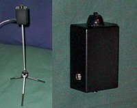
Completed Temperature Sensor
|
Construction Details
This is a simple, yet effective temperature meter, designed to give an analog DC output of 0-5 volts, proportionate to the surface temperature of the LM34. This is the same circuit design I use for Arcadia's surface temperature meter, and for the cost of construction (just a few dollars from DigiKey), it is a great meter. The circuit design is simple - the LM34 puts out 10mv per degree F, which then goes through a non-inverting amplifier. The signal is amplified 4 times, to give an output of 0 to 5 volts, from temperatures ranging from 0 to 125 degrees fahrenheit. Any discrete op amp will do - I have found LM358's to be very reliable and accurate for these type of meters, and can read almost to ground from a single power supply. The power supply can be from a power transformer, 9 volt battery, or any other 5-20 volt source. Also, as noted on the schematic, R1 and R2 can be interchanged for any resistor values that have a ratio close to 3. R3 is the value of R1 and R2 in parallel, (R1*R2) / (R1 + R2), which compensates for non-ideal input bias currents in the op amp. I have provided the basic conversion equation (assuming ideal resistor values) on the right of the schematic, but to obtain the most accurate conversion, use a Digital Multimeter to measure the values of R1 and R2 directly, and plug them into the formula given on the left of the schematic. Mounting the LM34 is described below, in an excerpt from the LM34's datasheet.
|
Mounting Details
- From LM34 Datasheet -
The LM34 can be applied easily in the same way as other integrated-circuit temperature sensors. It can be glued or cemented to a surface and its temperature will be within about 0.02°F of the surface temperature. This presumes that the ambient air temperature is almost the same as the surface temperature; if the air temperature were much higher or lower than the surface temperature, the actual temperature of the LM34 die would be at an intermediate temperature between the surface temperature and the air temperature. This is especially true for the TO-92 plastic package, where the copper leads are the principal thermal path to carry heat into the device, so its temperature might be closer to the air temperature than to the surface temperature. To minimize this problem, be sure that the wiring to the LM34, as it leaves the device, is held at the same temperature as the surface of interest. The easiest way to do this is to cover up these wires with a bead of epoxy which will insure that the leads and wires are all at the same temperature as the surface, and that the LM34 dieąs temperature will not be affected by the air temperature.
The TO-46 metal package can also be soldered to a metal surface or pipe without damage. Of course in that case, the ground terminal of the circuit will be grounded to that metal. Alternatively, the LM34 can be mounted inside a sealed-end metal tube, and can then be dipped into a bath or screwed into a threaded hole in a tank. As with any IC, the LM34 and accompanying wiring and circuits must be kept insulated and dry, to avoid leakage and corrosion. This is especially true if the circuit may operate at cold temperatures where condensation can occur. Printed-circuit coatings and varnishes such as Humiseal and epoxy paints or dips are often used to insure that moisture cannot corrode the LM34 or its connections. These devices are sometimes soldered to a small, light-weight heat fin to decrease the thermal time constant and speed up the response in slowly-moving air. On the other hand, a small thermal mass may be added to the sensor to give the steadiest reading despite small deviations in the air temperature.
<- Back to Main How-To Page
Disclaimer
Disclaimer: The author(s) of these articles, inventors, host(s) and sponsor(s) of this site are not responsible in any way for damages, direct or indirect, resulting from your performing, attempting to perform, or inability to perform, the construction and/or modifications described here. If you follow the instructions on this website carefully, your project should be successful, but we are not responsible for any damages done as the result of building this project!
Though the building/modification instructions are offered free of cost to the public on this website, the author/designer/inventors of this procedure and devices still retain all copyrights on the projects featured here. In other words, just because you built it doesn't mean you invented it! We offer you these projects as a way to improve your own research, and share with the world the knowledge we have been so fortunate to obtain at our research sites. The only thing we ask in return is to give the appropriate inventors credit when asked who came up with the idea.
Text and banner links, and donations are always greatly appreciated and welcomed. By reading these how-to pages, and attempting these projects you automatically agree to this disclaimer. We hope you find good use for this information, and good luck with your projects!
|
|